- sources
- shader = code running on your GPU
- like the most low level frontend code you’ll ever do lmao
- everything in a game is rendered in a shader, absolutely ubiquitous, many diff types of shaders that does different things
- completely unrelated to textures (input data that shaders can use)
- shaders take data (such as textures), does a bunch of math, and outputs that onto your screen
- we will focus on shaders that render graphics on your machine
- Textures are just images. Shaders produce the actual pixels on the screen, textures are just a source of information they use. Shaders take the mesh data and textures as well as the lights and they put the pixels on the screen.
- Some examples and user studies
Structure of a shader
.shader- the unity file of the shader
- Properties
- Properties u pass in
- set of input data
- colors, values, textures
- u should define these properties using a material
- Properties implicitly passed in
- the mesh you will use
- and usually the matrix for the mesh (contains the transform data of where the object is, how it’s rotated/scaled etc))
- Properties u pass in
- Subshader
- You can have multiple subshaders in a single shader file
- ex) a subshader meant to be more optimized to run on low end platforms
- if u have multiple u can pick one depending on your situation
- Contains Pass
- sometimes contains multiple passes
- lots of shaders that are NOT multiple passes
- this is where the shader code is happening
- usually what u will be using (written in HLSL)
- vertex shader
- fragment shader (sometimes called pixel shader)
Basic flow of the graphics pipeline
Vertex shader
At a high level, the vertex shader’s job is to determine where each vertex of a 3D model should appear on the screen.
- The vertex shader processes each vertex of your mesh individually (like a
for-eachloop over all vertices). - It is responsible for determining where each vertex should appear on the screen.
- The vertex shader does not have access to other vertices—each vertex is processed independently.
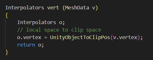
- Transformation
- In local space (a.k.a. object space), vertices are defined relative to the model itself.
- The vertex shader transforms these local space coordinates into clip space using the Model-View-Projection (MVP) matrix
- Clip space is a normalized coordinate system ranging from -1 to 1 in both x, y, and z (except w, which is used for perspective division).
- if u want to, you can modify these vertices (usually we don’t tho)
- code in unity
GPU
- Primitive assembly - Takes the transformed vertices and connects them into triangles
- Viewport transformation - Converts triangles from clip space → screen space
- converts coordinates to Normalized Device Coordinates (NDC)
- visible area is mapped to a standardized coordinate system (typically ranging from -1 to 1 in each axis), and then to screen coordinates based on the viewport settings
- Rasterization - Breaks triangles into fragments (pixels that need to be shaded).
- Interpolates vertex attributes (like normals, UVs, colors) for each pixel.
- Interpolation further discussed later
Fragment Shader
- foreach loop for every fragment (kind of like each pixel)
- Determines the final color of each pixel inside the triangle.
- Outputs the final color for the pixel to be drawn.
- u can write code to define how exactly that would look
In Unity
- there are many diff types of shaders in unity, we will start with unlit shader
- The basic u need to just apply texture to mesh
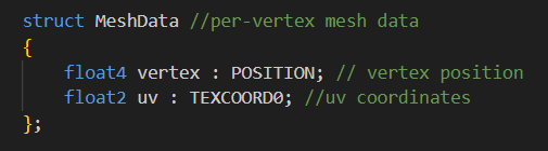
struct MeshData→ A structure that holds data for each vertex.- Each vertex in a mesh has:
float4 vertex : POSITION;- Stores the position of the vertex in 3D space.
float4means 4D vector (x, y, z, w).POSITIONis a semantic, which tells the GPU that this represents a vertex position.
float2 uv : TEXCOORD0;- Stores the UV texture coordinates.
float2means 2D vector (u, v).TEXCOORD0tells the GPU that this is the first set of texture coordinates.
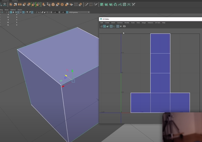
- uv coordinates
- very general, you can use these for almost anything
- quite often they’re used to map textures to objects
- u usually have some 2d coordinate system which is defining where do we want to map a 2d texture onto this 3d object
- Each UV set defines how a texture is mapped onto the surface of a 3D model
- Sometimes, one UV set isn’t enough because different textures need different mappings. An example:
TEXCOORD0→ Used for the main texture (albedo).TEXCOORD1→ Used for a lightmap, which stores precomputed lighting.
- When rendering a 3D model, each vertex has additional data associated with it, like:
- Position (to know where it is in space).
- UV coordinates (to map textures correctly).
- Normals (for lighting).
- vectors that describe the direction a surface is facing.
- the direction the vertex is pointing, usually used for shading to make things look smooth (or not smooth)
- Colors (if per-vertex coloring is used).
Interpolator
- “the data we want to interpolate”
- data that gets passed from the vertex shader to the fragment shader (it has to exist in this struct)
- Any data passed from the vertex shader to the fragment shader gets interpolate by the GPU.
- Vertex Shader runs per vertex, and this data is stored in this struct
struct v2f
{
	float4 vertex : SV_POSITION; // clip space position
	float2 uv : TEXCOORD0; //
};-
SV_POSITION→ Special semantic that stores clip-space coordinates (needed for rendering). -
TEXCOORD0→ This is just a generic interpolator (it often holds UVs, but can be used for anything).
-
Key points
- The fragment shader runs per pixel, not per vertex—so the GPU needs to blend the data across the triangle’s surface.
- If we pass a normal from the vertex shader to the fragment shader, the values at the edges (vertices) remain the same, but in-between pixels get a blended normal.
- in the fragment shader, u don’t actually have access to individual vertices, all u have is the interpolated data for any given fragment you’re rendering
-
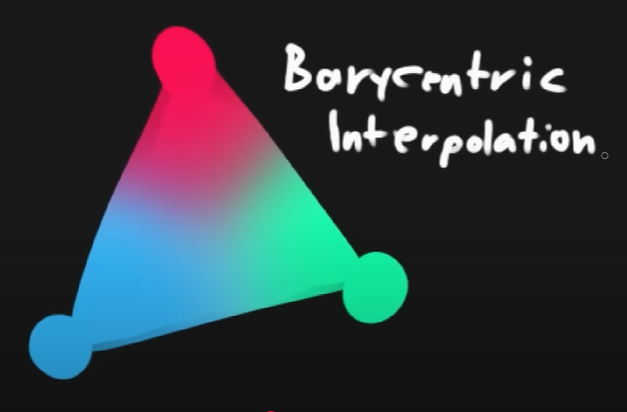
This is the classic triangle
-
The reason the color is blending like this is because you supplied some color data in each of the corners of the triangle and the fragment shader blends that data
-
A lerp for 3 points in 3d space → barycentric interpolation (will happen even tho u might not want this)
-
bool - 0 or 1
-
float - 32 bit float
- just use this 99% of the time… use float until you have to optimize
-
half - 16 bit float
-
fixed (lower precision) - about 12? useful for -1 to 1 range
- almost legacy at this point lol
- some platforms dont even support half and fixed
-
Vector ver: float4 → half4 → fixed4
- float4 is a vector of four 32-bit floats (like float4(x, y, z, w)).
-
Matrix ver: float4x4 → half4x4 → fixed4x4
SV_Target
- a semantic used in fragment shaders (also called pixel shaders)
- tells the GPU where the fragment shader should write its output.
- In Unity shaders,
SV_Targetmeans the color will be written to the framebuffer (render target).- Framebuffer is a memory buffer that stores the final color values before being displayed on screen